Point-to-Point via Wireless Local Loop
Provider- & Price overview for your location

STRONG PARTNERS
Savecall knows the market and works together with all carriers. We find the best solution for your network.
WLL
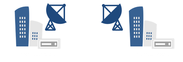
Point-to-point via wireless local loop is a high-performance site networking solution based on Wireless Local Loop technology (wireless local loop technology “WLL”).
It offers a permanent connection between two locations in connected or neighboring company buildings as a complete solution for transparently transmitting IP packets.
The service includes the provision of a wireless local loop connection between the neighboring locations which are generally installed on the roof of the customer’s building. A line of sight between the two wireless local loop locations must be ensured in order to establish the radio connection.
Benefits of WLL
Real media redundancy
In conjunction with a terrestrial back-up connection, you are equipped to combat any disrupting factors.
Flexibility
Back-up-ready: can be quickly expanded by different back-up connections for real-time media redundancy without complications.
Point-to-Point via Wireless Local Loop
Point-to-point via wireless local loop is ideal for companies that
- want to connect neighboring locations to each other
- require very high bandwidths
- do not have fiber glass connections between the buildings
- desire high availabilities
- place special value on media redundancy
- require fast implementation and provision of high bandwidths
- also ideal for coupling computing centers on the premises
Functionality of a Point-to-Point wireless local loop connection
Wireless local loop connections are established via a so-called air interface. Wireless local loop offers scalable bandwidths between 2 Mbit/s and 1,000* Mbit/s on the upstream and downstream.
- In a Wireless-Local-Loop, the path from customer location A to customer location B is bridged by a radio field, e.g. at a frequency of 26 GHz.
- The antennae must have an uninterrupted line of sight at the customer locations.
- An antenna with a transmitter/receiver unit, the outdoor unit (ODU) has to be installed on the roof at the customer’s end location.
- The customer connects its network to an interface on the indoor unit (IDU). The ODU and IDU are connected via a cable.
Requirements for a wireless local loop connection at the customer’s location
- Maximal 30 km distance to the next wireless local loop location
- Line of sight between the customer location and the wireless local loop location
- Permit to install the wireless local loop system and the corresponding work on the building by means of a building owner declaration (BOD)
- Building-related requirements (statics, etc.) that make the installation of a wireless local loop system possible.
*the information regarding the max. achievable bandwidths may differ depending on the provider!
Overview of all providers
| Providers | Product |
 |
QSC-WLL-direct-line |
 |
Scaltel Ethernet directional radio |
Implementation
- In a Wireless-Local-Loop, the path from the roof position of a base station to the end customer’s location is bridged via a radio field, e.g. using a frequency of 26 GHz.
- The antenna at the roof position at the customer’s location must have an uninterrupted line of sight with the base station.
- An antenna with a transmitter/receiver unit, the outdoor unit (ODU) is mounted on the roof at the end customer’s location.
- The end customer connects its network to an interface on the indoor unit (IDU). The ODU and IDU are connected via a cable.
General process
Internet services via directional radio are commissioned in stages:
- Review of the general availability
- Capacity/bandwidth query at the regional network planning agency
- Signing the contract, obtaining the BOD and commissioning order
- Commissioning the line of sight check
- Site inspection to clarify the structural measures
Line of Sight (LOS check)
- Line-of-Sight (LOS) means that the antennas at the respective end points of a radio path can “see” each other.
- LOS connections are usually implemented in systems with high data rate, availability and range of path requirements. Wireless local loop paths are always LOS.
- LOS must be checked for each individual section on site.
Environmental impacts on wireless local loop (WLL) connections
Radio systems are subject to environmental influences which don’t play a role with fiber glass or copper networks:
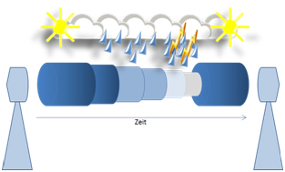
- Rain insulation: in the event of heavy rains which can arise in conjunction with storm fronts, the transmission rate of the radio path can be reduced.
- Wind loads on the antennae can lead to misalignment, in particular on wireless local loop paths. properly built roof constructions, the wind load generally doesn’t play a role.
The systems used are capable of increasing the availability of the transmission path using automatic and uninterrupted modulation changes: in the event of bad weather conditions, the system will be switched to a less sensitive modulation.
In turn, radio systems are not affected by typical error and failure sources in the grid network:
- Cable breakage due to underground construction.
- Reduced transmission rates due to crosstalk between unshielded dual copper wires.
- In practice, radio systems can achieve availabilities comparable to those of fiber glass or copper networks.
Interception protection
Wireless local loop connections
In order to intercept a wireless local loop connection (transmitter/receiver direction), first the complicated interception technology would have to be positioned near the direct line of sight between the base station and the customer antenna and could therefore be quickly located.
The right frequency – inaccessible to third parties
In order to intercept a radio link, the attackers have to know the frequency bands assigned by the Internet service provider and the frequencies used for the link since there are hundreds of different frequency channels in the same geographic area. The technology used is still based on a digital transmission that makes interception difficult in principle due to the digital data stream. Furthermore, the special wireless local loop technology is very expensive and is only available from a few manufacturers.
Combined procedure for proper operation
The “customer – base station” and “base station – customer” connections are established using a variety of combined modulation and demodulation procedures. This digital procedure converts or encrypts the data so the transmitter and corresponding receiver can work properly (equation, carrier recovery and timing recovery).
Digital data packets – secure transmission
The FEC (Forward Error Correction) encoder in the multiplexer and demultiplexer is applied to the already existing data and ensures the digital data is securely evaluated later. The data is sent to the separation process during which the bytes from the service channel and that of the data are processed separately. This means an attacker would have to sort the desired data packets out of he radio traffic in the wireless local loop field. In order to generate the transmitted bit stream from the received radio signals, the proprietary modulation of the provider-specific technology must also be known.
Air instead of earth – Optimum transmission
Restoring the original information from an intercepted data stream is de facto impossible without precise knowledge of the aforementioned security measures implemented by the WLL provider. The security of the transmitted data is thus significantly higher than with conventional, cable-based transmissions. These connections largely utilize standardized and thus commonly known transmission methods for which the technology is installed on the ground floor of the customer’s building. The radio technologies used are installed on the roofs. On the one hand, these are not accessible to everyone and on the other, they are installed in locked system cabinets. The data is also forwarded via wireless local loop or fiber glass until the signal has been introduced to the backbone of the Internet service provider (ISP).
Contact our expert now
 Ronald Bals
ICT Expert
Tel: 089 / 219 914 810
E-Mail: datendienste@savecall.de